
Steve Flanges stands out as a top-notch manufacturer and supplier of ANSI B16.36 flanges right here in Canberra, Australia. With a wealth of experience in the industry, they focus on crafting high-quality flanges that adhere to ANSI standards, guaranteeing precision, durability, and reliability for a variety of industrial uses. They cater to sectors like oil and gas, petrochemicals, power generation, and water treatment. By blending cutting-edge manufacturing techniques with rigorous quality control, Steve Flanges delivers flanges that meet exact specifications. Their dedication to quality and customer satisfaction has made them a go-to choice for ANSI B16.36 flange solutions in Canberra and the surrounding areas.

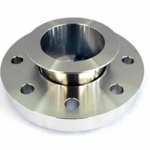
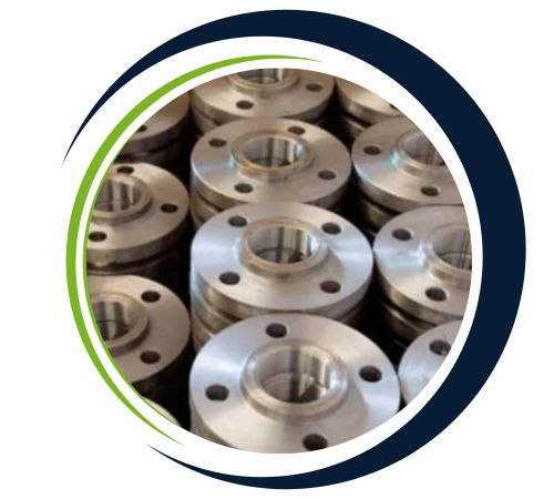
ANSI B16.36 flanges are usually constructed from high-quality materials like carbon steel, stainless steel, and alloy steel, making them highly resistant to corrosion and possessing superior strength. Their content may differ based on application requirements, with typical grades being ASTM A105, A182 F304, and F316. These flanges possess better mechanical properties, including better tensile strength, yield strength, and toughness. ANSI B16.36 flanges, which are used for orifice and pressure relief services, are strong even at severe stress conditions. Their strength and reliability enable them to find application in crucial piping systems across various industries.
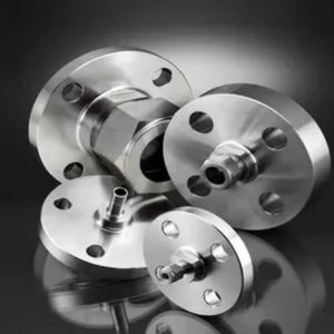
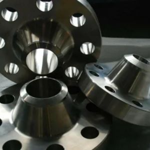
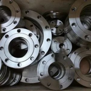
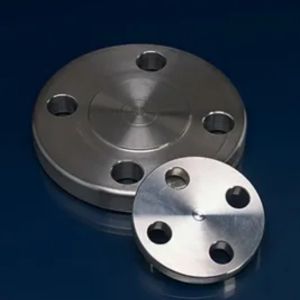
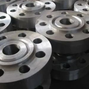
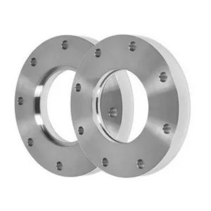
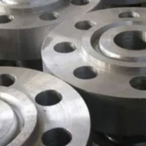
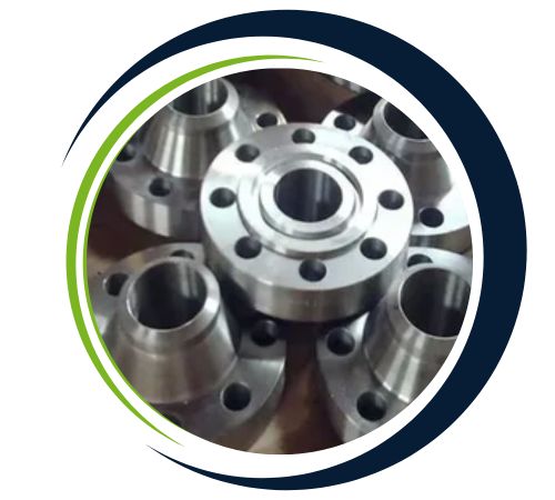
The ANSI B16.36 flanges produced by Steve Flanges are made from top-grade carbon steel, stainless steel, and alloy steel, offering impressive mechanical properties such as high tensile strength, toughness, and resistance to corrosion. Built to endure high pressure and temperature conditions, these flanges promise long-lasting performance even in the toughest industrial settings. With precise material composition, controlled heat treatment, and strict compliance with ANSI B16.36 standards, they ensure durability and dependable operation. Each flange goes through thorough inspection and quality assurance to meet international safety and performance standards.
| Size Range | 1/2″ (15 NB) to 48″ (1200NB) DN10~DN5000 |
|---|---|
| DIN | 6Bar 10Bar 16Bar 25Bar 40Bar / PN6 PN10 PN16 PN25 PN40, PN64 |
| JIS | 5K, 10 K, 16 K 20 K, 30 K, 40 K, 63 K |
| UNI | 6Bar 10Bar 16Bar 25Bar 40Bar |
| EN | 6Bar 10Bar 16Bar 25Bar 40Bar |
| Main Types | Threaded / Forged / Plate /Screwed |
| Flange supporting material | Ring Joint, Gasket, Flange Bolts |
| Test Certificates | EN 10204/3.1B Raw Materials Certificate 100% Radiography Test Report Third Party Inspection Report, etc |
| Most Common Types |
|
| Production technique |
|
| Connect Type/ Flange Face Type | Ring Type Joint (RTJ), Raised Face (RF),Large Male-Female (LMF), Flat Face (FF),Small Male-Female (SMF), Lap-Joint Face (LJF), Large Tongue & Groove, Small Tongue, Groove |
| Special design | As per your drawing AS, ANSI, BS, DIN and JIS 15 NB (1/2″) to 200 NB (8″) Equal and Reducing Configurations Threaded Flange, Socketweld Flange, Slip-On Flange, Blind Flange, Weld Neck Flange |
| Test | Direct-reading Spectrograph, Hydrostatic testing machine, X-ray detector, UI trasonic flaw detector, Magnetic particle detector |
| Equipment | Bending machine, Press machine, electric bevelling machine, Pushing Machine, Sand-blasting machine etc |
| Origin | Indian / West Europe / Japan / USA / Korean |
| Material Test Certificates (MTC) as per EN 10204 3.1 and EN 10204 3.2, Test Certificates certifying NACE MR0103, NACE MR0175 | |
| NPS | O | C | R | X | A | Y | TT | No. of holes | Diameter of holes | Diameter of bolts | Diameter of bolt circle | |
|---|---|---|---|---|---|---|---|---|---|---|---|---|
| inch | 1″ | 4.88 | 1.5 | 2 | 2.12 | 1.32 | 3.25 | 01/04/07 | 4 | 0.69 | 5/8″ | 3.5 |
| Millimeter | 124 | 38.1 | 50.8 | 53.8 | 33.5 | 82.6 | 6.4 | 17.5 | 15.9 | 88.9 | ||
| Inch | 1 1/2″ | 6.12 | 1.5 | 2.88 | 2.75 | 1.9 | 3.38 | 01/04/07 | 4 | 0.81 | 3/4″ | 4.5 |
| Millimeter | 155.4 | 38.1 | 73.2 | 69.9 | 48.3 | 85.9 | 6.4 | 20.6 | 19.1 | 114.3 | ||
| Inch | 2″ | 6.5 | 1.5 | 3.62 | 3.31 | 2.38 | 3.38 | 01/04/07 | 8 | 0.69 | 5/8″ | 5 |
| Millimeter | 165.1 | 38.1 | 91.9 | 84.1 | 60.5 | 85.9 | 6.4 | 17.5 | 15.9 | 127 | ||
| Inch | 2 1/2″ | 7.5 | 1.5 | 4.12 | 3.94 | 2.88 | 3.5 | 01/04/07 | 8 | 0.81 | 3/4″ | 5.88 |
| Millimeter | 190.5 | 38.1 | 104.6 | 100.1 | 73.2 | 88.9 | 6.4 | 20.6 | 19.1 | 149.4 | ||
| Inch | 3″ | 8.25 | 1.5 | 5 | 4.62 | 3.5 | 3.5 | 03/08/07 | 8 | 0.81 | 3/4″ | 6.62 |
| Millimeter | 209.6 | 38.1 | 127 | 117.3 | 88.9 | 88.9 | 9.5 | 20.6 | 19.1 | 168.1 | ||
| Inch | 4″ | 10 | 1.5 | 6.19 | 5.75 | 4.5 | 3.62 | 01/02/07 | 8 | 0.81 | 3/4″ | 7.88 |
| Millimeter | 254 | 38.1 | 157.2 | 146.1 | 114.3 | 91.9 | 12.7 | 20.6 | 19.1 | 200.2 | ||
| Inch | 6″ | 12.5 | 1.5 | 8.5 | 8.12 | 6.63 | 3.94 | 01/02/07 | 12 | 0.88 | 3/4″ | 10.62 |
| Millimeter | 317.5 | 38.1 | 215.9 | 206.2 | 168.4 | 100.1 | 12.7 | 22.4 | 19.1 | 269.7 | ||
| Inch | 8″ | 15 | 1.62 | 10.62 | 10.25 | 8.63 | 4.38 | 01/02/07 | 12 | 1 | 7/8″ | 13 |
| Millimeter | 381 | 41.1 | 269.7 | 260.4 | 219.2 | 111.3 | 12.7 | 25.4 | 22.2 | 330.2 | ||
| Inch | 10″ | 17.5 | 1.88 | 12.75 | 12.62 | 10.75 | 4.62 | 01/02/07 | 16 | 1.12 | 1″ | 15.25 |
| Millimeter | 444.5 | 47.8 | 323.9 | 320.5 | 273.1 | 117.3 | 12.7 | 28.4 | 25.4 | 387.4 | ||
| Inch | 12″ | 20.5 | 2 | 15 | 14.75 | 12.75 | 5.12 | 01/02/07 | 16 | 1.25 | 1 1/8″ | 17.75 |
| Millimeter | 520.7 | 50.8 | 381 | 374.7 | 323.9 | 130 | 12.7 | 31.8 | 28.6 | 450.9 | ||
| Inch | 14″ | 23 | 2.12 | 16.25 | 16.75 | 14 | 5.62 | 01/02/07 | 20 | 1.25 | 1 1/8″ | 20.25 |
| Millimeter | 584.2 | 53.8 | 412.8 | 425.5 | 355.6 | 142.7 | 12.7 | 31.8 | 28.6 | 514.4 | ||
| Inch | 16″ | 25.5 | 2.25 | 18.5 | 19 | 16 | 5.75 | 01/02/07 | 20 | 1.38 | 1 1/4″ | 22.5 |
| Millimeter | 647.7 | 57.2 | 469.9 | 482.6 | 406.4 | 146.1 | 12.7 | 35.1 | 31.8 | 571.5 | ||
| Inch | 18″ | 28 | 2.38 | 21 | 21 | 18 | 6.25 | 01/02/07 | 24 | 1.38 | 1 1/4″ | 24.75 |
| Millimeter | 711.2 | 60.5 | 533.4 | 533.4 | 457.2 | 158.8 | 12.7 | 35.1 | 31.8 | 628.7 | ||
| Inch | 20″ | 30.5 | 2.5 | 23 | 23.12 | 20 | 6.38 | 01/02/07 | 24 | 1.38 | 1 1/4″ | 27 |
| Millimeter | 774.7 | 63.5 | 584.2 | 587.2 | 508 | 162.1 | 12.7 | 35.1 | 31.8 | 685.8 | ||
| Inch | 24″ | 36 | 2.75 | 27.25 | 27.62 | 24 | 6.62 | 01/02/07 | 24 | 1.62 | 1 1/2″ | 32 |
| Millimeter | 914.4 | 69.9 | 692.2 | 701.5 | 609.6 | 168.1 | 12.7 | 41.1 | 38.1 | 812.8 |
| Size in In. | Size in Millimeter | Outer Diameter | Flange Thickness | Hub OD | Weld Neck OD | WN Lengtd | RF Dia. | RF Height | PCD | Hole dia | No of Bolts | Bolt Size UNC | RF Stud Lengtd | Hole Size | ISO Stud Size | Weight in kg |
| A | B | C | D | E | F | G | H | I | ||||||||
| 1 | 25 | 125 | 36.6 | 54 | 33.4 | 81 | 50.8 | 2 | 88.9 | 6.4 | 4 | 5/8 | 125 | 3/4 | M16 | 4.5 |
| 1 1/2 | 40 | 155 | 36.6 | 70 | 48.3 | 84 | 73 | 2 | 114.3 | 6.4 | 4 | 3/4 | 135 | 7/8 | M20 | 6.5 |
| 2 | 50 | 165 | 36.6 | 84 | 60.3 | 84 | 92.1 | 2 | 127 | 6.4 | 8 | 5/8 | 125 | 3/4 | M16 | 7 |
| 2 1/2 | 65 | 190 | 36.6 | 100 | 73 | 87 | 104.8 | 2 | 149.2 | 6.4 | 8 | 3/4 | 135 | 7/8 | M20 | 7.5 |
| 3 | 80 | 210 | 36.6 | 117 | 88.9 | 87 | 127 | 2 | 168.3 | 9.5 | 8 | 3/4 | 135 | 7/8 | M20 | 9.4 |
| 4 | 100 | 255 | 36.6 | 146 | 114.3 | 90 | 157.2 | 2 | 200 | 12.7 | 8 | 3/4 | 135 | 7/8 | M20 | 13.2 |
| 6 | 150 | 320 | 36.6 | 206 | 168.3 | 98 | 215.9 | 2 | 269.9 | 12.7 | 12 | 3/4 | 135 | 7/8 | M20 | 14.6 |
| 8 | 200 | 380 | 39.7 | 260 | 219.1 | 110 | 269.9 | 2 | 330.2 | 12.7 | 12 | 7/8 | 145 | 1 | M24 | 30 |
| 10 | 250 | 445 | 46.1 | 321 | 273 | 116 | 323.8 | 2 | 387.3 | 12.7 | 16 | 1 | 165 | 1 1/8 | M27 | 41 |
| 12 | 300 | 520 | 49.3 | 375 | 323.8 | 129 | 381 | 2 | 450.8 | 12.7 | 16 | 1 1/8 | 180 | 1 1/4 | M30 | 62 |
| 14 | 350 | 585 | 52.4 | 425 | 355.6 | 141 | 412.8 | 2 | 514.4 | 12.7 | 20 | 1 1/8 | 185 | 1 1/4 | M30 | 84 |
| 16 | 400 | 650 | 55.6 | 483 | 406.4 | 144 | 469.9 | 2 | 571.5 | 12.7 | 20 | 1 1/4 | 195 | 1 3/8 | M33 | 111 |
| 18 | 450 | 710 | 58.8 | 533 | 457 | 157 | 533.4 | 2 | 628.6 | 12.7 | 24 | 1 1/4 | 205 | 1 3/8 | M33 | 138 |
| 20 | 500 | 775 | 62 | 587 | 508 | 160 | 584.2 | 2 | 685.8 | 12.7 | 24 | 1 1/4 | 215 | 1 3/8 | M33 | 171 |
| 24 | 600 | 915 | 68.3 | 702 | 610 | 167 | 692.2 | 2 | 812.8 | 12.7 | 24 | 1 |
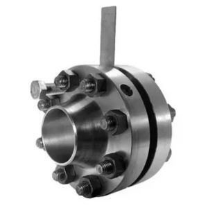
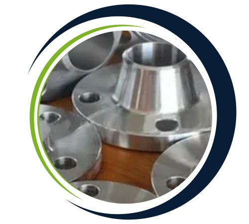
ANSI B16.36 flanges are chiefly utilized in piping systems that need to measure flow or provide pressure relief. They are particularly intended to fit orifice plates for measuring flow rates of gases, liquids, or steam. Typically applied in oil and gas, chemical processing, power generation, and water treatment industries, they provide precise flow control and monitoring for various applications. Their ability to handle high temperatures and pressures makes them ideal for applications with high performance requirements. ANSI B16.36 flanges are also required in systems that require pressure taps and are often coupled with control systems for efficient process control.
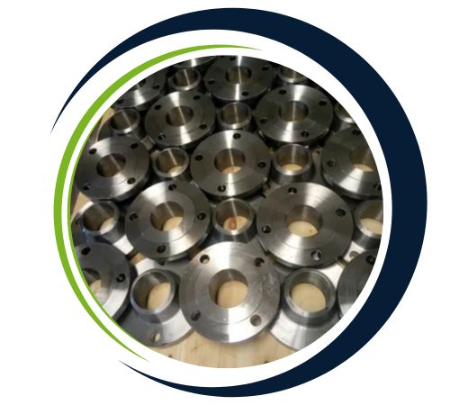

These ANSI B16.36 flanges find their place in pipelines, oil and gas projects, chemical plants, power generation facilities, and water treatment systems across Canberra, Australia. They play a vital role in connecting pipes, valves, pumps, and other equipment in high-pressure and high-temperature systems, allowing for seamless maintenance, inspection, and system expansion without any operational hiccups. Engineers and contractors trust Steve Flanges’ products to ensure safe, efficient, and long-lasting fluid and gas flow, making them an essential part of robust and reliable systems.
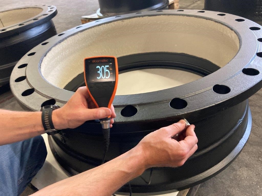
We are renowned for delivering products with precise, accurate dimensions. Each product undergoes thorough testing, both destructive and non-destructive, to ensure quality before being shipped to our customers.

Our team is ready to assist you. Contact us for any queries or personalized solutions.
Copyright 2024 Steve Flanges, All rights reserved